2D and 3D Networks
Topological Classification in 2D and 3D Networks
For the description of low-connectivity crystalline structures (such as covalent solids, MOFs – Metal Organic Frameworks, etc.), especially in the case of species that form infinite bi- or tri-dimensional architectures, a topological approach proves very useful for analyzing the structure. This approach requires identifying the centers (nodes) of the network within the structure, which cause branching (thus involving at least three connections), and then simplifying the structure by reducing atoms, chains, or groups of atoms that only serve to connect these nodes to the role of simple spacers.

Once the appropriate simplifications have been made to reduce the crystalline structure into a schematic form, the next step is to classify the network by relating the structure to a specific topology.
The main goal of this topological analysis of crystalline structures is to uniquely classify the structure and the network of connections present in the crystal through the taxonomy of polyhedra and periodic networks.
From a mathematical point of view, the problem can be related to the tessellation of space.
In plane geometry, tessellations refer to filling space with one or more geometric figures repeated infinitely without overlaps.
These geometric figures (called "tiles") can be polygons or prisms, depending on whether the tiled space is 2D or 3D.
Therefore, a generally useful method of proceeding is to consider structural models as made up of tiles. The tiles we are interested in are polygonal in the case of coverings of a surface (a 2D space) or polyhedra or cages in the case of three-dimensional Euclidean space.
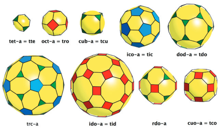
2D tiles can be familiar polygonal shapes, squares, hexagons, etc., that cover a flat surface, or, in the case of the tessellation of the surface of a sphere, the structure corresponds to a convex polyhedron.
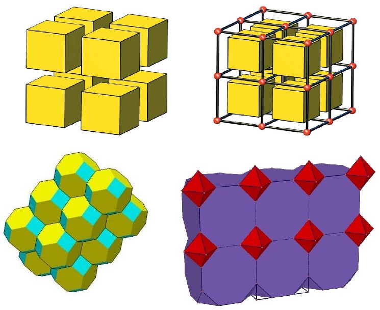
A familiar example of 3D tessellation is the filling of space with cubes. The Wigner-Seitz cells are also an example we have encountered of space tessellation. The tessellation of 3D space can also be achieved by combining various polyhedra.
In a proper two-dimensional (2D) tessellation, the edges of the tiles are shared exactly between pairs of tiles (edge-to-edge).
In a proper three-dimensional (3D) tessellation, the faces of the tiles are shared exactly between pairs of tiles (face-to-face).
The set of vertices and edges of the tiles forms a network — that is, a simple connected graph — and it is said that the tessellation gives rise to a network.
Each tessellation corresponds to a specific and unique network, making the systematic enumeration of tessellations a powerful method in crystalline structures for classifying the connection networks found.
However, it is important to note that the relationship between tessellations and networks is not one-to-one: a given network can be generated topologically by an infinite number of different tessellations. Nevertheless, all these tessellations can be reduced to a unique special form known as the natural tessellation (analogous to the relationship between a lattice and a unit cell).
For example, the simplest and most regular tessellation of Euclidean space is the filling of space with identical cubes. The symmetry of this tessellation and its corresponding network is described by the space group Pm m. It is also possible to tessellate space by using double cubes (cubes sharing a face) or various combinations of cubes, resulting in an infinite number of different arrangements.
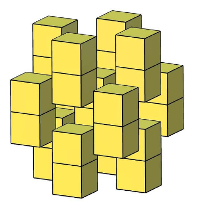
However, it is easy to see that all such multiple tiles will necessarily have lower symmetry, as some translational symmetries are lost. Thus, we can identify a unique natural tessellation that preserves the network symmetry, which in this case is the cubic tessellation.
Therefore, the main rule for identifying the natural tessellation is that the symmetry of the tile must match the symmetry of the network. Additional rules exist to help determine the natural tessellation in cases of lower symmetry.
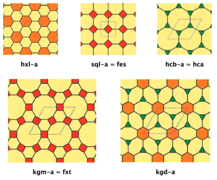
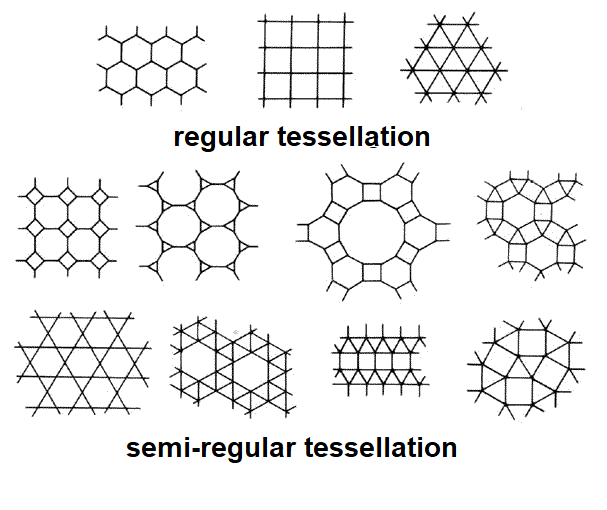
In two dimensions, regular tessellations are those formed using only a single type of regular polygon (all sides and angles equal), while semi-regular tessellations are constructed using multiple types of regular polygons.
A real chemical example that exhibits a planar hexagonal mesh network (also called a honeycomb) is graphene.
This architecture is also found in the arrangement of boron atoms in the simple hexagonal structure of AlB₂. In both cases, the hexagons are strictly planar, however many other examples of hexagonal structures can be associated with the same topology, even if the cycles are distorted or wavy, such as in elemental arsenic or black phosphorus (one of the three main allotropes of phosphorus, along with molecular white P₄ and the one-dimensional polymeric red form).
Structure of black phosphorus
There are numerous examples of structures with two-dimensional networks of square meshes also (with more or less wavy layers), such as PbO, LiOH, HgI₂ (red form), etc.
Structure of HgI₂
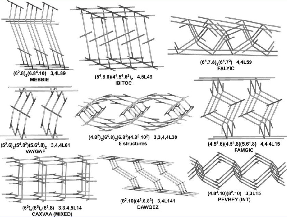
Structures with three-dimensional networks (3D) are more complex to classify, due to their enormous variety (several hundred 4-connected nets have been described in the literature).
For a systematic description of networks, it is essential to uniquely identify the topology using an appropriate notation.
The terms encountered in this context include:
-
Uni-nodal networks, where all vertices are topologically equivalent. Otherwise, we refer to bi-nodal, tri-nodal, etc., networks.
-
A circuit is a continuous closed sequence of edges and distinct vertices, starting and ending at the same vertex. Two edges that share a vertex define an angle at that vertex.
-
A p-connected node (connected to p nodes) possesses [p(p – 1)/2] angles, for each of which a large number of circuits can be found, each characterizable by the number of edges (or nodes) it contains.
For example, in the cube, for each 3-connected node with 3*(3–1)/2 = 3 angles, we can identify several closed circuits.
The elementary circuit (cycle) of a network is a sequence of vertices 1, 2, 3, … n, 1 such that (1,2), (2,3), … (n,1) are the edges, and no vertex (except the starting/ending one) appears more than once in the sequence.
The sum of two cycles is the set of edges (and their vertices) belonging to one or the other cycle, but not to both. More generally, this rule says that the result of summing n cycles is the cycle defined by the set of all edges that occur an odd number of times in the sum.
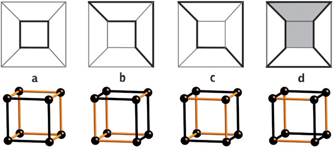
For example, in the case of the cube, Figure b shows a cycle that is the sum of two cycles (note the absence of the shared edge between the two faces defining the summed cycles), while Figure c shows a cycle that can be obtained from the sum of cycles a and b.
A ring is a cycle that cannot be expressed as the sum of two smaller cycles.
A strong ring is a ring that cannot be expressed as the sum of any number of smaller cycles.
For instance:
-
The cube in Figure a shows a strong ring.
-
The 6-membered cycle in Figure b, being the sum of two 4-membered cycles, is not a ring.
-
The 6-membered cycle in Figure c, which is the sum of three (not two) smaller cycles, is a ring, but not a strong ring.
-
The 8-membered cycle in Figure d, being the sum of a 6-membered (shaded) and a 4-membered cycle, is also not a ring.
In a 3D network, strong rings define cages (tiles) that partition the crystal space (tessellation).
As seen with the cubic lattice, the number of different tiles that can reconstruct a given network is infinite. However, we can consider the minimal cages (natural tiles), which are not sums of smaller tiles, to build the unique spatial partitioning called the natural tessellation.
The faces of the natural tiles are also called essential rings, forming a subset of strong rings.
One of the main notations used to classify and concisely present the most important geometric and topological properties of a tessellation is the Schläfli symbol.
The Schläfli symbol uses a recursive notation enclosed in curly braces, such as {p, q, r, ...}, where the n terms within describe regular polytopes in n-dimensional space.
-
For the tessellation of a 1D sphere (a circle) with a segment, {p} represents a regular polygon with p sides. Examples: {3} = equilateral triangle, {4} = square, etc.
-
For the tessellation of a 2D sphere, {p, q} refers to a pattern in which p-gons meet q times at each vertex. Examples: the five Platonic solids are described as:
-
Tetrahedron: {3,3}
-
Cube: {4,3}
-
Octahedron: {3,4}
-
Icosahedron: {3,5}
-
Dodecahedron: {5,3}
-
The same notation can describe regular tessellations of a plane, e.g.:
-
{3,6}: tiling with equilateral triangles
-
{4,4}: tiling with squares
-
{6,3}: tiling with hexagons
The Schläfli symbol {p, q, r} refers to a 3D space tessellation in which the {p, q} tiles meet r times along each edge. For example, the tessellation of 3D space with cubes is represented as {4,3,4}.
To describe 3D networks more broadly, including multi-nodal networks, Wells introduced the Point Symbol (PS).
In a network, a n-connected vertex can be identified through the PS, which indicates the shortest cycles associated with its [n(n – 1)/2] angles.
In general, the PS is written as:
(Aᵃ . Bᵇ . Cᶜ...)ⁿ (Xˣ . Yʸ . Zᶻ...)ᵐ …
Where:
-
A, B, C,… and X, Y, Z,… are numbers indicating the length of the cycles (number of edges).
-
a, b, c,… and x, y, z,… are the number of cycles of each type.
-
n, m,… is the number of times those nodes are present in the smallest repeating unit of the network.
If the superscript or subscript is equal to 1, it is omitted.
For example, consider the 2D graphene network, a regular 3-connected honeycomb. At each vertex, there are three hexagonal cycles (the shortest ones). Its point symbol is 6³.
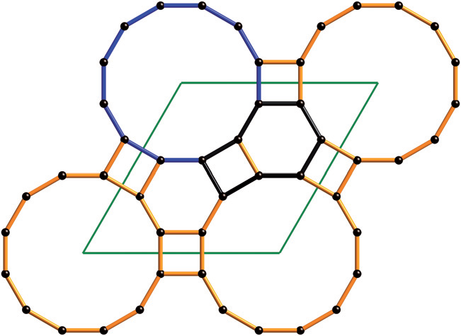
Let us now look at an example of a 3D, 3-connected, uni-nodal network corresponding to the structure of boron oxide (B₂O₃).
In this structure, 10-membered cycles converge at each vertex, so the Point Symbol (PS) is very simple: 10³.
Be careful not to confuse this with the Schläfli symbol {10,3} (a common mistake in the literature), which instead identifies a tessellation of hyperbolic space where three decagons meet at each vertex.
Other structures also have three 10-membered rings meeting at each vertex, and therefore also have PS 10³, such as SrSi₂ and α-ThSi₂. However, these structures have different topologies, and to distinguish them, Wells labeled them as 10³-a, 10³-b, and 10³-c.
For example, another case of ambiguity is found in the uni-nodal 4-coordinated network present in NbO and the arrangement of silicon atoms in quartz. Although both structures have different topologies, they share the same Point Symbol: 6⁴.8².
To better distinguish between such different networks/tessellations, a more detailed formalism was developed to more accurately report the topology of the network nodes.
In particular, to describe the local topology of the vertices of polyhedra and 2-periodic tessellations, the Vertex Symbol (VS) was introduced (also called vertex configuration or vertex type). This symbol lists, in cyclic order, the sizes of the polygons meeting at the vertices. For Archimedean solids (semi-regular polygons) or uni-nodal (semi-regular) plane tessellations, it takes the form A.B.C...., where A, B, C... indicate the number of edges (or sides) of the polygons that meet at the vertex, in sequence.
For example:
-
The cuboctahedron has VS 3.4.3.4
-
The truncated tetrahedron has VS 3.6² (a concise notation for 3.6.6)
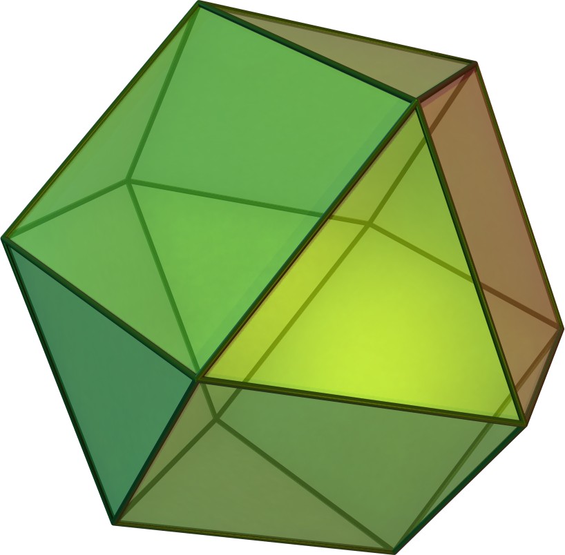
cuboctahedron truncated tetrahedron
To uniquely identify different tessellations, one starts from the smallest faces. It is also important to emphasize the significance of the order of numbers in this notation.
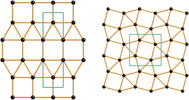
For example, the 2D networks in the figure below, although they share the feature of having three triangles and two squares meeting at each vertex, are characterized by completely different tessellations, represented by VS 3³.4² (3.3.3.4.4) and VS 3².4.3.4 (3.3.4.3.4).
This type of notation can be easily extended to structures with more than one type of vertex, such as Johnson solids or 2D multi-nodal tessellations.
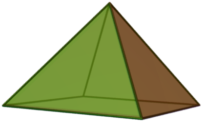
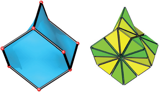
For example, the square-based pyramid can be represented with VS (3⁴)(3².4)₄.
It is important to keep in mind that even with this formalism, not all ambiguities are resolved. In fact, the vertex symbol (VS) does not always describe a unique structure.
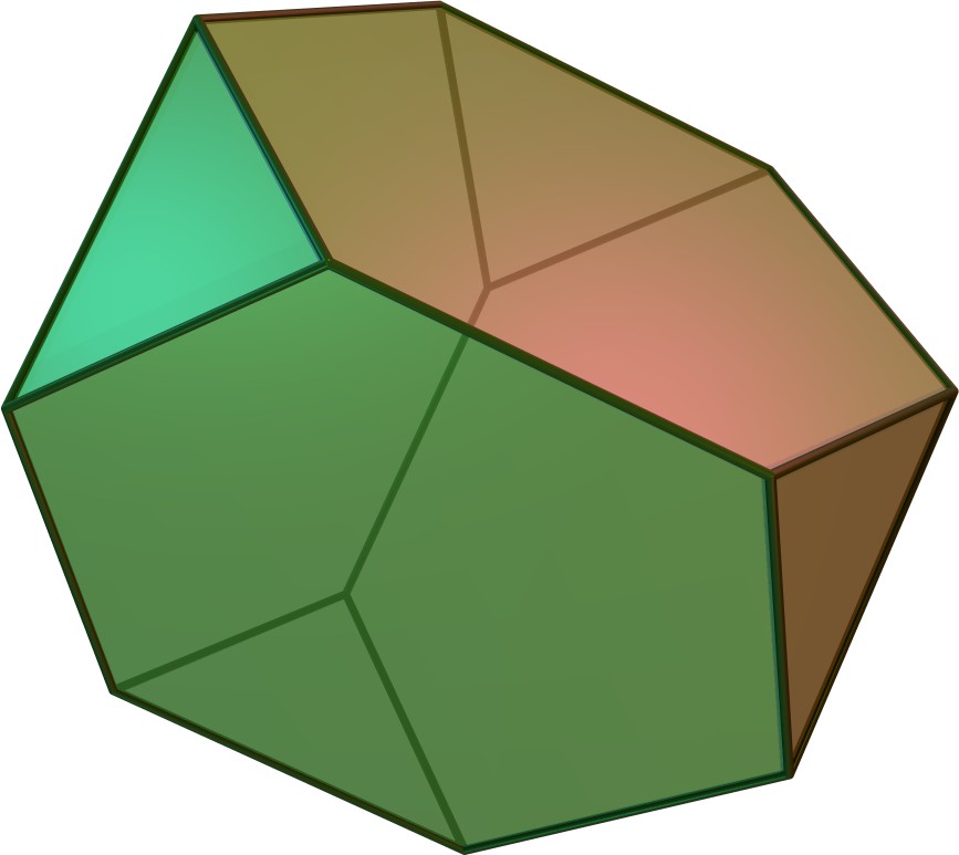
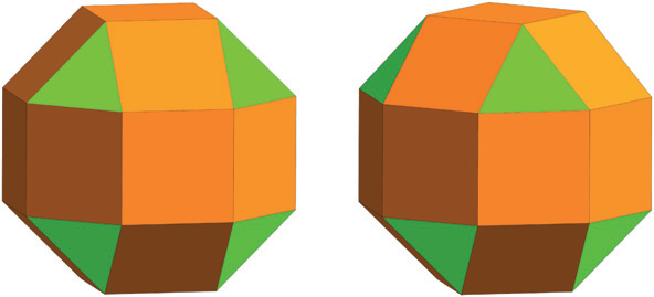
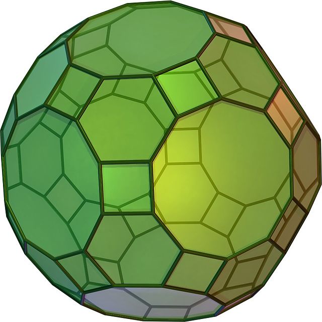
For example, in the figure below showing two distinct polyhedra—the rhombicuboctahedron (an Archimedean solid with Oh symmetry) and the elongated square gyrobicupola (a Johnson solid with D4h symmetry)—both solids are represented by the same VS: 3.4³.
It should be noted that, for the faces of a polyhedron or in a 2-periodic tessellation, the rings to be considered are not necessarily the shortest cycles.
For example, the figure above shows the tessellation with VS 4.6.12: for the angle defined by the 12-sided faces, a shorter 8-membered cycle can be identified, which is the sum of the 4- and 6-membered cycles.
Similarly, in the polyhedron with VS 4.6.10, which corresponds to the truncated icosidodecahedron (an Archimedean solid), a shorter 8-membered cycle can also be identified for the angle that includes the 10-membered ring.
However, as we have seen, not all cycles are rings, and in the VS notation, the shortest rings, not the shortest cycles, should be considered.
But not necessarily strong rings. For example, the polyhedron of the square pyramid with VS (34)(32.4)4 has a square base, which is the sum of four strong 3-term rings (the triangular faces). Therefore, the VS refers to the shortest rings, not necessarily strong rings (or even the shortest cycles).
The VS notation has been extended with this logic of the shortest rings also to 3D networks. For example, for 3-coordinated vertices, with 3 angles, it takes the form Aa.Bb.Cc, indicating that in the first angle, there are a short rings of A terms, in the second angle, there are b short rings of B terms, and in the third angle, there are c short rings of C terms.
With this notation, networks like SrSi2 and α-ThSi2, both having PS 103, can be discriminated. In fact, the SrSi2 network has 5 short 10-term rings for each angle, while in α-ThSi2, there are 2, 4, and 4 short 10-term rings for the three angles. Therefore, their respective VS are 105.105.105 and 102.104.104.
In the case of networks with 4-coordinated nodes, there are 6 angles to consider, and it has been proposed to group the angles into three pairs of opposite angles (those without a common edge).
One advantage of this convention (widely used for the description of zeolites) is that the VS also provides information about the network's configuration.
For higher coordinations, the VS can become very complex, as the angles, equal to n*(n-1)/2, grow rapidly. In such cases, the PS may be simpler.
Finally, there is an additional symbol, the Delaney symbol (D-symbol), which is an extension of the Schläfli symbol.
For this D-symbol, the tessellations are first sectioned into chambers. In two dimensions, a chamber is defined by a triangle with vertices: at the center of the tessellation, at the center of an edge, and at a vertex of the edge. In three dimensions, the chamber is a tetrahedron with vertices: at the center of the tessellation, at the center of a face, at the center of an edge of that face, and at a vertex of the edge.
The figure shows how the tessellation of the diamond structure is divided into chambers.
The number of different types of chambers in a tessellation is called complexity, and it is used to describe the type of network.
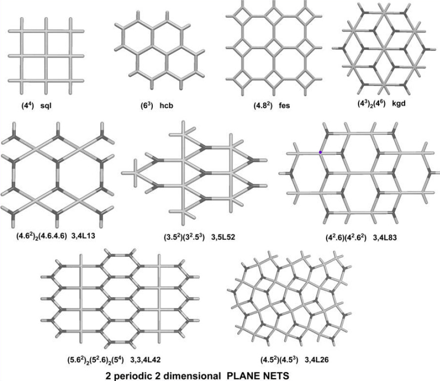
Examples of 2D networks.
Esempi di network 3D